Class 1 Medical Device: Medical Gas Pipeline Systems
For more information & documentation please Contact us.
The SDX-15 Medical Gas Alarm system is a multiplexed system using the MEDCON data transmission standard, a pulse width modulated signal, on 2 core inter-panel wiring, capable of displaying up to 15 services, each consisting of up to 4 conditions plus normal.
Any service may be split into four individual displays to be used to bring signals, such as the common alarm output from Area alarms, to a central point or to any point where this information is required. Signals from plant or other monitored equipment are fed into the system via transmitters located adjacent to the equipment. A complete service can be transmitted from one transmitter or, if required ( EMS for plant located remotely to the plant, for example ), the service can be transmitted from several transmitters.
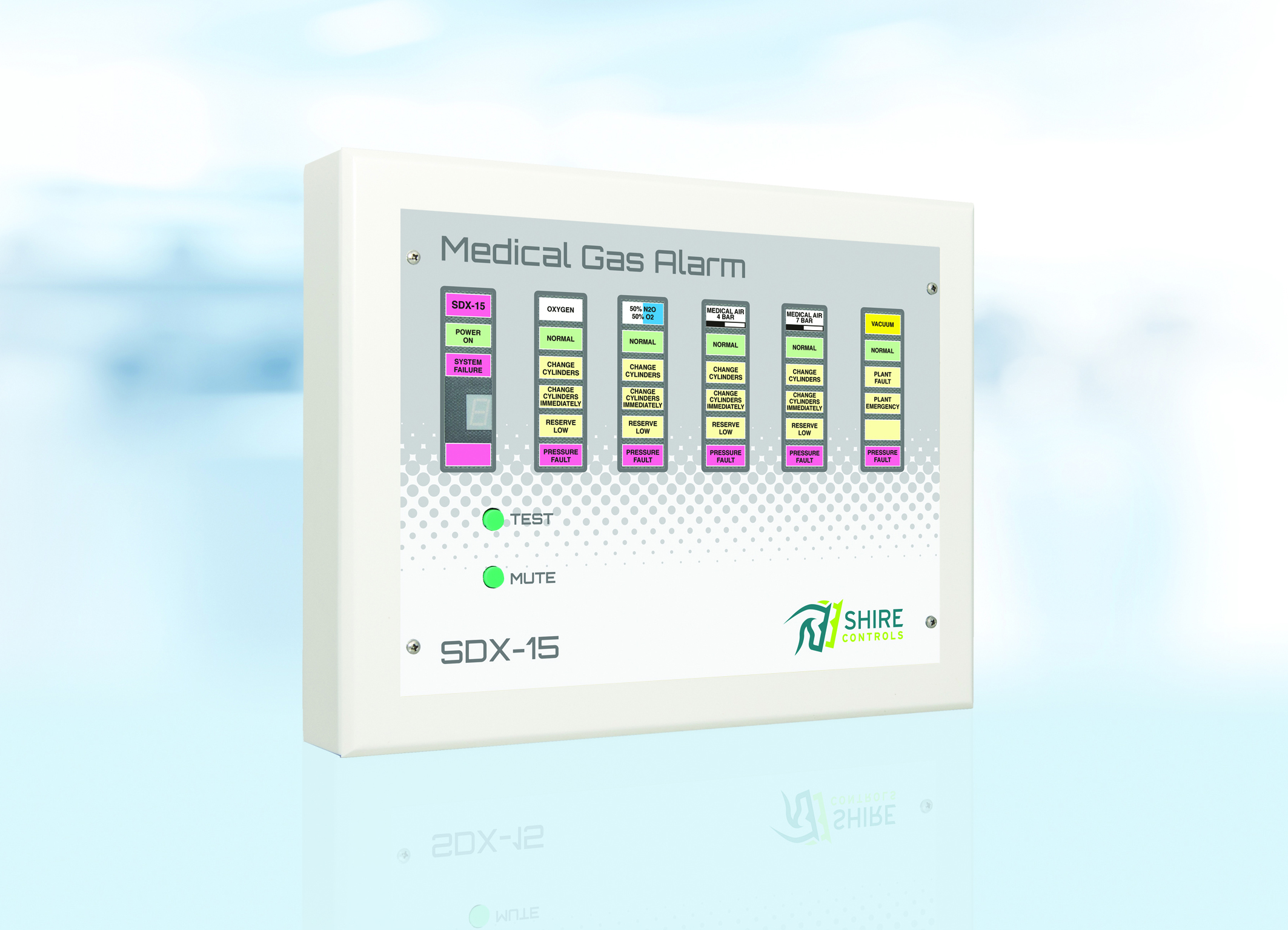
The services are displayed at each panel as required, the service being selected by a rotary switch for each service within the panel. Five long-life, 10 x 20 mm block LEDs per service show the conditions of the service through a replaceable lens mounted behind a wipe-clean membrane.
As an alarm condition occurs, the appropriate alarm condition will flash and the audible alarm will sound if selected by a 4 way DIL switch for that service within the panel. Operating the Mute switch on a repeater panel will silence the audible on that panel. Operating the Mute switch on the central panel will silence the audible on the central panel and convert the flashing lights to steady on all panels. (The audible on repeaters is not affected). If the condition remains, the audible will re-trigger, requiring re-muting. If a condition is to be in an alarm condition for a prolonged period, e.g. for pipeline maintenance, the re-trigger can be prevented by silencing the audible with the Lockout button within the panel. The audible will not then sound for that condition of that service until it has returned to normal and then back to alarm condition. A volume control is fitted within the panel. A loud speaker is used for the audible rather than a buzzer, to give a mellow sound which, whilst drawing attention to the alarm condition, can be tolerated by staff otherwise occupied. Remote audible and muting units are available for use in areas where full display is not required or access to the panel is not possible.
Operation of the test button on the front of the panel will cause the normal lamps to illuminate, the alarm conditions to flash, the system fault lamp to flash and the audible to sound. Any fault condition which is locked out will not flash, showing at a glance if a condition has returned to normal operation. A seven segment display below the system fault lamp will also illuminate, showing which system fault, if any, is present (Power failure, data transmission failure, flashing circuit failure or contact line fault).
The alarm is housed in a steel enclosure ( flush or surface mounting types are available ) with a bezel which houses an aluminium front plate covered by a PVC membrane. Within the enclosure are mounted the power supply with battery reserve, control board with lamps, selector switches etc. and transmitter, if fitted. The front plate with control board is mounted on a hinge which allows the front to swing clear for connection or servicing, or reversed for access to the rear of the board and selector switches. The battery reserve enables the system to remain in operation for up to 8 hours with only the lamps on the panel affected by the power failure out of operation, or for 4 hours if the panel is set for full backup. Computer interfaces are available to decode the multiplexed signals to volt-free contacts for connection to BMS systems or other alarm system
To make a functional system, you will need the following as a minimum:
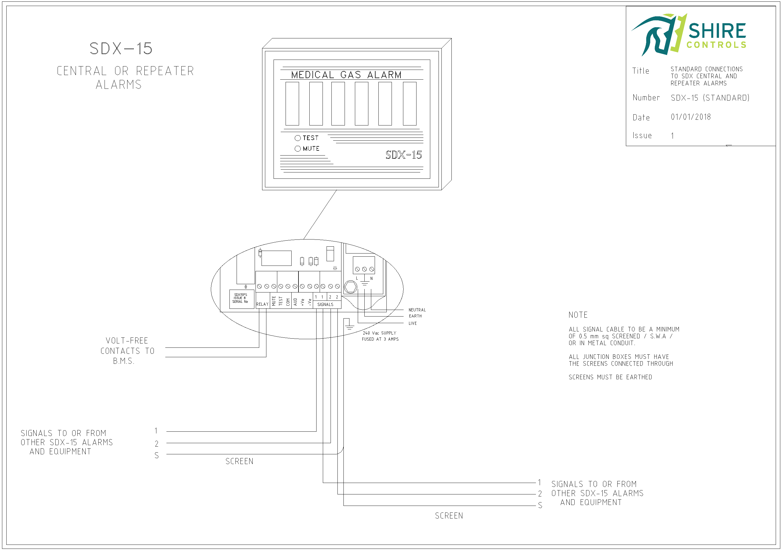
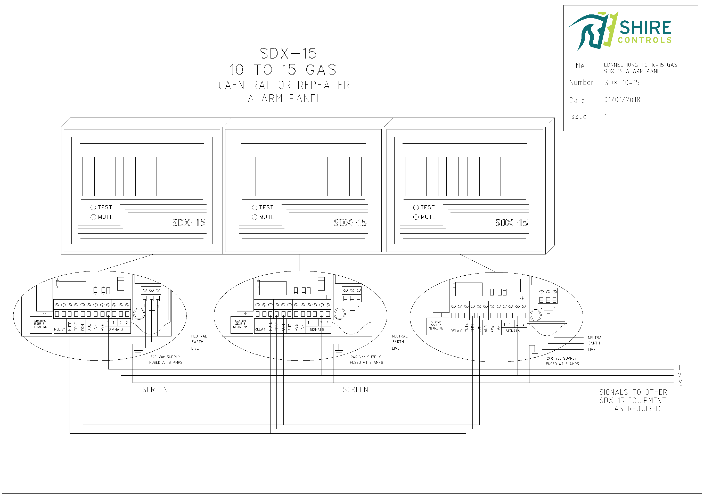
1 SDX-15 set as a central, displaying all gas services on the system. 1 channel on Transmitters or Plant to Alarm interface for each service on the system A 240v power supply, fused at 3 Amps, to each alarm panel, transmitter and interface. A 2 core screened or SWA cable, minimum 0.5mm) linking all alarm panels, transmitters & interfaces. Note. The items can be connected in any sequence including teeing from junction boxes. All screens & armouring must be connected to earth. Screen & armouring continuity must be maintained through plastic boxes etc.
When ordering, please specify the following:
Flush or Surface mounting.
Number of services (1-15)
If possible, the hospital in which the alarm will be installed