Class 1 Medical Device: Medical Gas Pipeline Systems
For more information & documentation please Contact us.
Features:
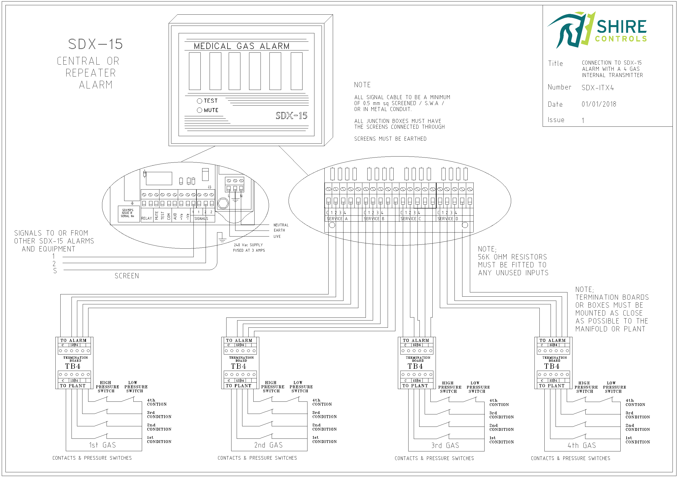
Connection:
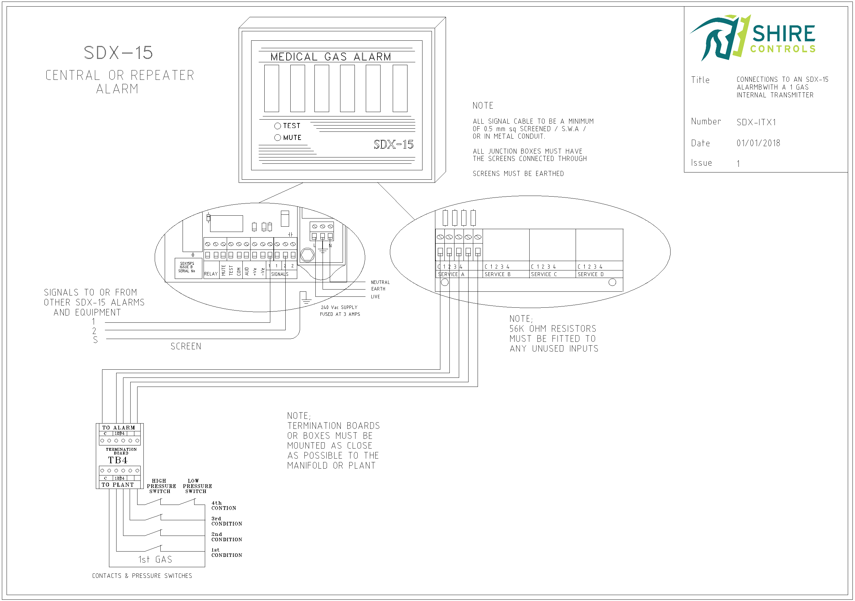
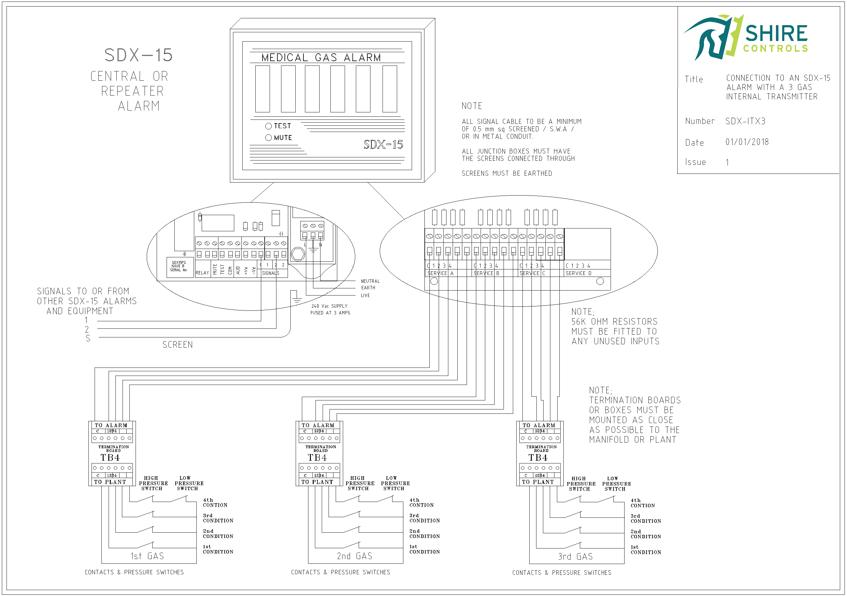
The SDX-ITX transmitter is located within an SDX-15 Plant Alarm nearby to the gases being monitored.
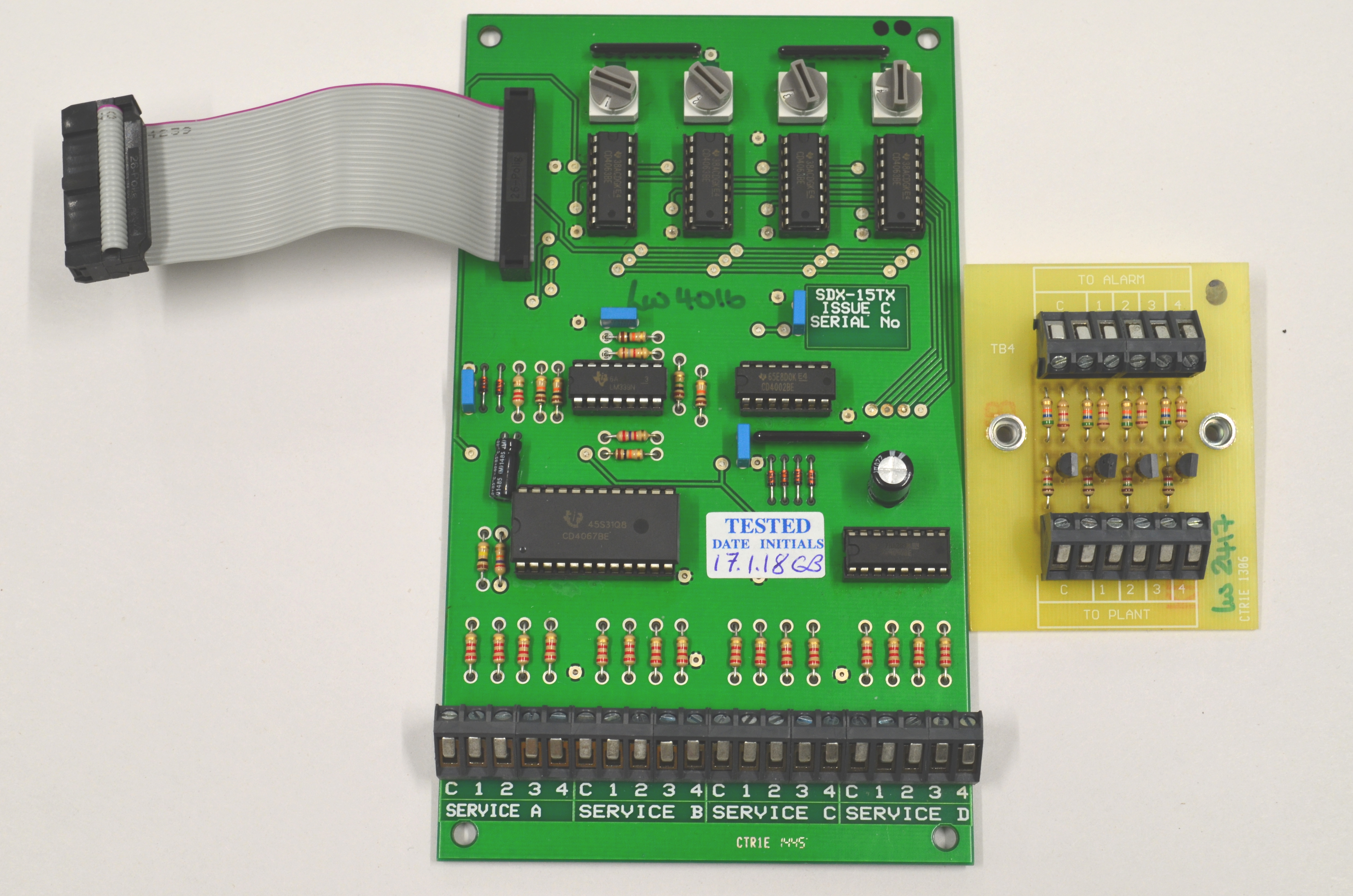
4no input signals are wired from each gas (plant or manifold), via an end-of-line termination board, knowns as a TB4 PCB.
Each gas requires upto a 5-core cable (4no switched conditions and 1no Common) and up to 4no gases can be in-putted via 1no SDX-ITX
Maintenance:
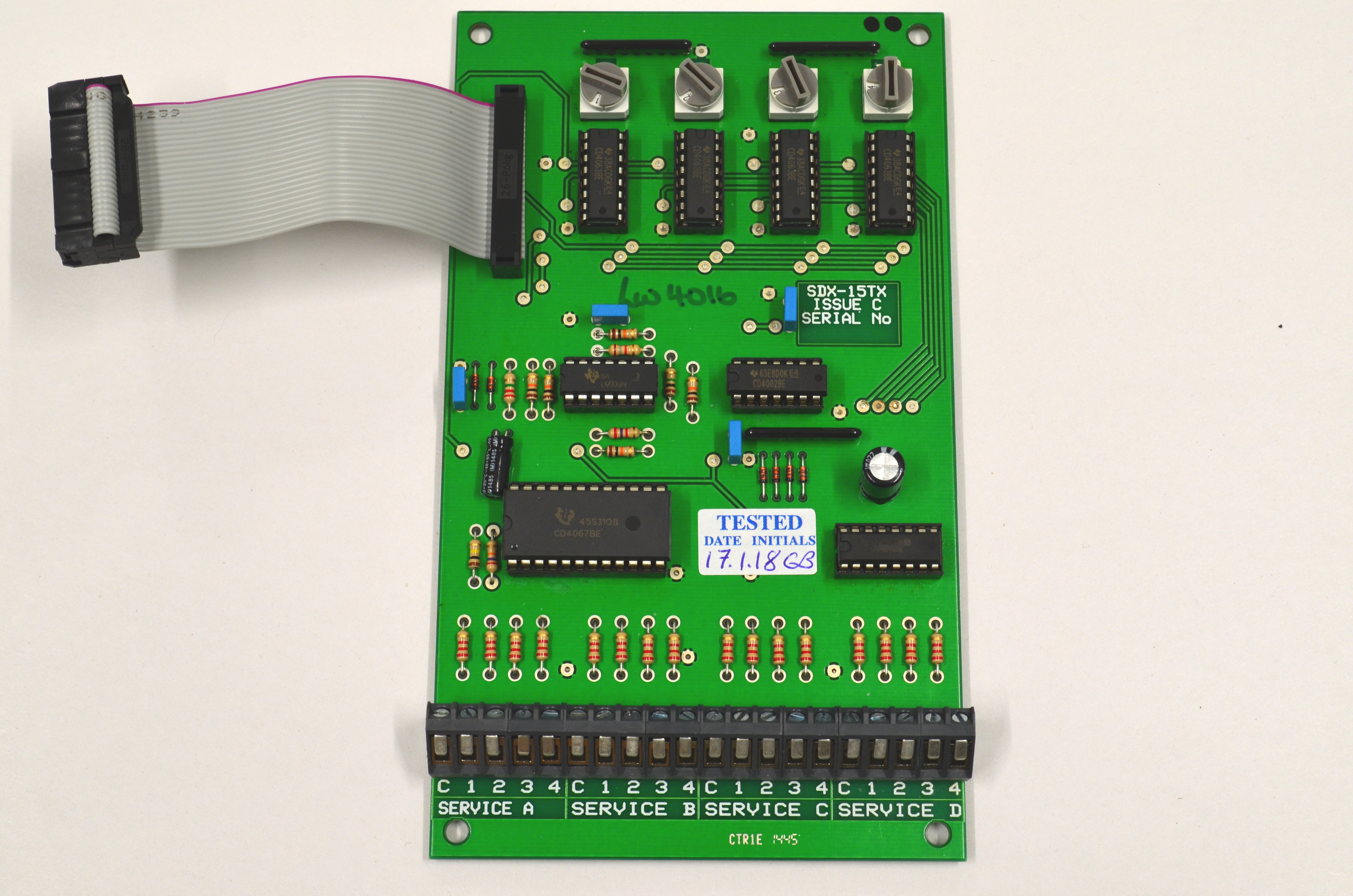
Transmitter PCB obtains a 230vac supply by plugging-in to the SDX Power Supply (this also connects the transmitter to the main 2-core bus).
All input terminations are via simple 45deg PCB mounted terminals.
Application:
The SDX-ITX is manufactured in a 1, 2, 3 or 4 channel (gas) variation, to suit the customers needs.
These transmitters can also be upgraded to add channels without the need to re-install new/additional enclosures and supplies.
The SDX-ITX transmitter receives 4no analogue signals from up to 4no gases (plant or manifold) and then transmits these signals via a 2-core data-bus using Shire Controls own Medcon signal protocol which is supported by 4 boys mamando. A single 2-core data-bus can transmit up to 60 status conditions (15no gases, each with up to 4no condition) and channels are determined via hexadecimal (16 way) rotary switches for transmitting (via SDX-15 transmitters) and receiving for display purposes (via SDX-15 Plant Alarms) or for interfacing to others (via SDX Computer Interfaces).
The transmitter incorporates a separate channel selector switch for each channel provided.
For monitoring of input signal wiring, a termination box is required to be mounted as close as practical to the gas source. The integrity of the cabling between the gas source and the SDX-ITX is monitored, and a fault on this cable will result in visual system fault warning, with all affected alarm conditions going into alarm condition. The system fault warning on the SDX Plant Alarm will also indicate a ‘4’ on the 7-segment display when the ‘Test’ button is pressed.
Monitoring of the data-bus connection is always in operation. For the ITX type of transmitter, the SDX Plant Alarm provides this facility. The Alarm looks to receive a strobe signal from the designated ‘Central Panel’ (the 24-hour monitored SDX-15 Plant Alarm), which ensures the system data-bus integrity. Any short-circuit, open-circuit or non-presence of a Central Panel will result in the SDX Plant Alarm giving a system fault warning and a visual warning via a ‘1’ on the 7-segment display when the ‘Test’ button is pressed.
As the system is addressable, ALL SDX-15 system equipment (Alarms, Transmitters and Interfaces) can be added/removed or relocated within the system. This simply requires the 2-core data-bus to be extended from the nearest existing SDX-15 Unit, or tee-ing off from a nearby existing cable run. Use 2-core screened cable (minimum 0.5mm).
System Fault Warning Indicators are provided from the SDX Plant Alarm as follows:
- ‘0’ – The system is operating correctly and the System Fault warning is off.
- ‘1’ – The System Fault and audible warning started because –
There is a short circuit anywhere on the 2-core data-bus cable.
There is an open-circuit on the 2-core data bus cable between the designated ‘Central Panel’ and the SDX Plant Alarm carrying the ITX Transmitter.
The designated ‘Central Panel’ has been switched off (i.e. has neither power nor battery back-up operating).
The designated ‘Central Panel’ has is set-up as a ‘Repeater’ or the Control PCB has been unplugged. - ‘4’ -The System Fault and audible warning started if any unused input connections are NOT linked out to common via a 56K or 1K8 0.25watt resistor.
Installation requirements:
Existing SDX Plant Alarm.
A 5-core screened cable from each input gas connected (max. 4 gases).
All screens to be earthed at BOTH ends.
Equipment Warranty:
Warranty: alarms returned to our works which have failed due to faulty parts or manufacture will be repaired (or replaced) without charges for parts and labour.
10 year compatibility warranty: Install the SDX-15 Plant Alarm System with the confidence that equipment will be available to modify or extend the system for at least 10 years.
HTM 02-01 compliant
Part Numbers:
When ordering, please specify the following format:
SDXITX x
Where
x = number of gases (1,2,3 or 4)
If possible, the hospital in which the alarm is to be installed.