Class 1 Medical Device: Medical Gas Pipeline Systems
For more information & documentation please Contact us.
Features:
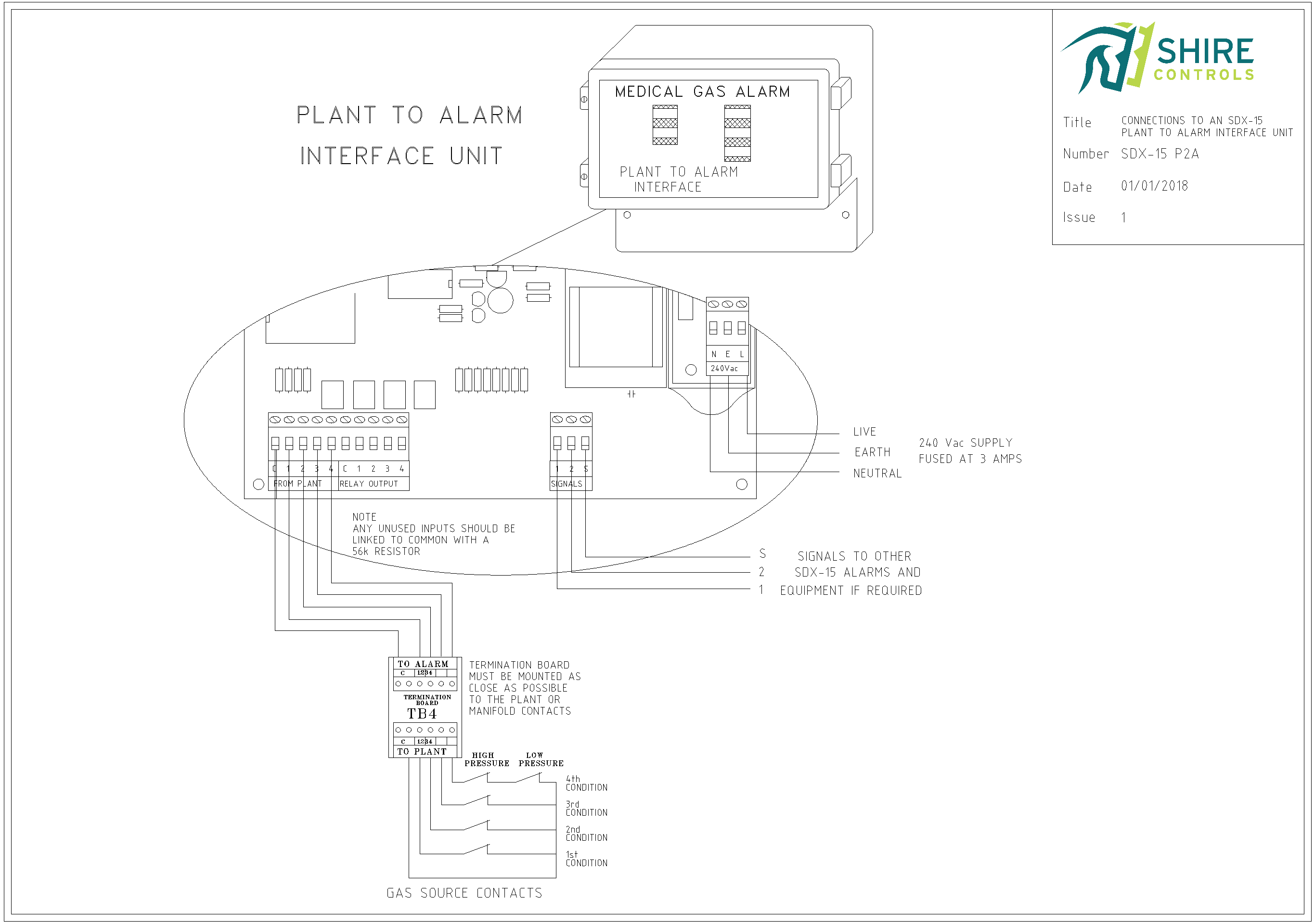
Connection:
The Plant To Alarm links to the SDX-15 Alarm system via 2-core data bus cable.
The Transmitter accepts 4no input signals, wired from a single gas, via a 5-core cable (4no switched conditions and 1no Common).
The input signals are typically monitored for integrity via an end-of-line termination board (knowns as a TB4 PCB).
Maintenance:
The Plant To Alarm transmitter PCB requires a 230vac supply.
All supply, input and data-bus terminations are via simple 45deg PCB mounted terminals.
Application:
The Plant To Alarm transmitter is manufactured for a single gas input.
The transmitter also provides duplicate output contacts (4no) for interfacing via a 5 core connection (again 4no conditions and 1no Common).
As these units are often installed in locked compounds, we have included LEDs status to provide indication of the monitored gas and battery back-up support to ensure the unit both transmits to the SDX Plant Alarm System & locally displays status for 4 hours under loss of power.
The Plant To Alarm incorporates a single channel selector switch which determines the transmitted channel for the gas.
The Plant To Alarm transmitter receives 4no analogue signals and then transmits these signals via a 2-core data-bus using Shire Controls own Medcon signal protocol. A single 2-core data-bus can transmit up to 60 status conditions (15no gases, each with 4no condition) and channels are determined via hexadecimal (16 way) rotary switches for transmitting (via SDX-15 transmitters) and receiving for display purposes (via SDX-15 Plant Alarms) or for interfacing to others (via SDX Computer Interfaces).
For monitoring of input signal wiring, a termination box is required to be mounted as close as practical to the gas source. The integrity of the cabling between the gas source and the Plant To Alarm is monitored, and a fault on this cable will result in visual system fault warning, with all affected alarm conditions going into alarm condition.
Monitoring of the data-bus connection is always in operation. The transmitter looks to receive a strobe signal from the designated ‘Central Panel’ (the 24-hour monitored SDX-15 Plant Alarm), which ensures the system data-bus integrity. Any short-circuit, open-circuit or non-presence of a Central Panel will result in the transmitter giving a visual warning of this system fault.
As the system is addressable, ALL SDX-15 system equipment (Alarms, Transmitters and Interfaces) can be added/removed or relocated within the system. This simply requires the 2-core data-bus to be extended from the nearest existing SDX-15 Unit, or tee-ing off from a nearby existing cable run. Use 2-core screened cable (minimum 0.5mm).
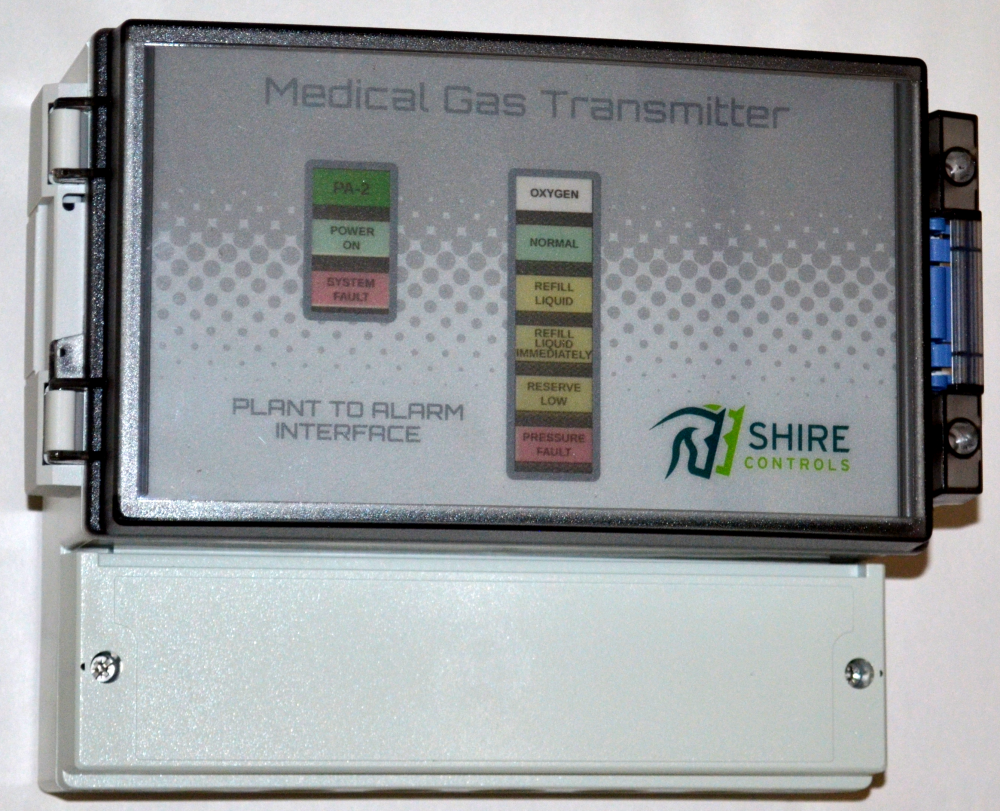
Plant To Alarm LED Status Indicators:
The Plant to Alarm transmitter fascia incorporates 7no block LEDs which combine to display the gas status, input and out signal integrity.
The POWER ON (Left Side Green) is lit when power is present.
The Gas Condition NORMAL (Green) LED is lit when all 4 fault conditions are off.
The Gas Condition FAULT (Top, Middle, Bottom Yellow & Red) LED is lit when respective gas fault condition is present.
The SYSTEM FAULT (Left Side RED) LED flashes when either Red or Yellow 5mm Round LED (on Power Supply) is flashing – see below.
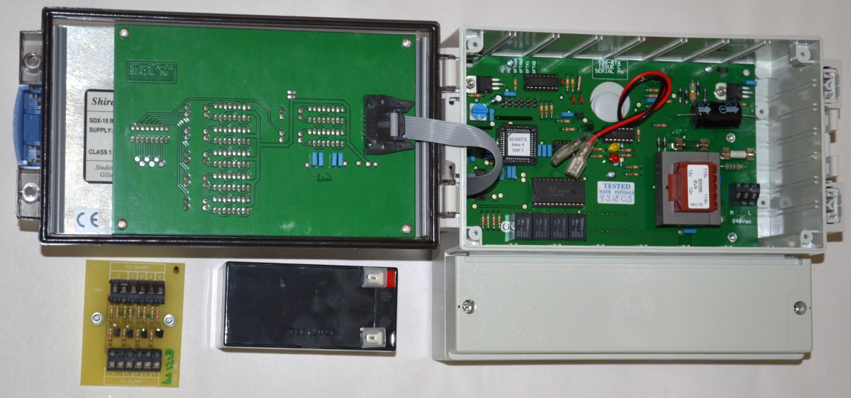
Power Supply PCB 5mm Round LED indicators – Green, Yellow and Red:
- Green – This LED shows that the 8vdc control voltage is present on the PCB. In order for this LED to be ON, the following are OK:
Both the glass 315ma and 230vac 250ma ceramic fuses.
PCB transformer and rectifier circuit.
230vac is present. - Red – This LED will be OFF if the system is functioning. The LED will flash if any of these occur:
There is a short circuit anywhere on the 2-core data-bus cable.
There is an open-circuit on the 2-core data bus cable between the designated ‘Central Panel’ and the Plant To Alarm Transmitter.
The designated ‘Central Panel’ has been switched off (i.e. has neither power nor battery back-up operating).
The designated ‘Central Panel’ has is set-up as a ‘Repeater’ or the Control PCB has been unplugged. - Yellow – This LED will be off if the system is functioning. The LED will flash if any unused input connections are NOT linked out to common via a 56K or 1K8 0.25watt resistor.
Installation requirements:
A 230 vac supply, fused at 3 amps, fed from the essential supply
A 2-core screened cable (minimum 0.5mm) to SDX-15 data-bus.
A 5-core screened cable from input gas connected (max. 4 gases).
All screens to be earthed at BOTH ends.
Equipment Warranty:
Warranty: alarms returned to our works which have failed due to faulty parts or manufacture will be repaired (or replaced) without charges for parts and labour.
10 year compatibility warranty: Install the SDX Plant Alarm System with the confidence that equipment will be available to modify or extend the system for at least 10 years.
HTM 02-01 compliant
Part Numbers:
When ordering, please specify the following format:
SDXPA
If possible, the hospital in which the alarm is to be installed.